What you will learn
Description
Content

What you will learn
The students will learn the basic tools of Solidworks. Also they will get a thorough knowledge of Sketch, Part, Assembly, and Surface environments of Solidworks.
Description
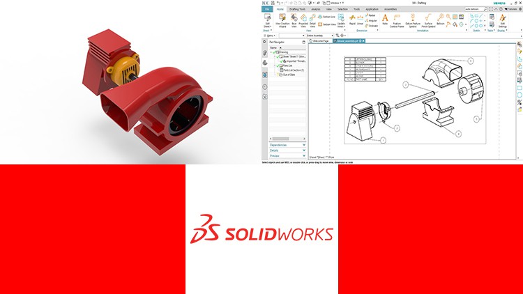
SOLIDWORKS is a very productive 3D CAD software tool. It helps to design various products and services, testing them in very cost effective way like Model and prototype testing as you learned earlier in engineering degree class.
The Solidworks have wide range of applications in industries such as
This course will help you in understanding and learning the basic and advanced tools of the software. You will get a thorough knowledge and hands on experience on Sketch, Part, Assembly and Surface Environments of SOLIDWORKS.
Subscribe to latest coupons on our
Telegram channel.
Content
Introduction
Introduction to SOLIDWORKS
User Interface of SOLIDWORKS
Customizing Command Managers and Toolbars in SOLIDWORKS
Drawing Sketches For Solid Models
Starting a New File and Opening an Existing one in SOLIDWORKS
Entering the Sketching Environment
Creating Line, Centerline, and Midpoint Line
Creating Circles
Creating Arcs
Creating Rectangles
Creating Polygons
Creating Splines
Creating Slots
Placing Points
Creating Ellipses and Elliptical Arcs
Creating Parabolic and Conic Curves
Creating Equation Driven Curves
Drawing Display Tools
Deleting Sketching Entities
Practice Example 1
Practice Example 2
Practice Example 3
Editing and Modifying Sketches
Trimming Entities
Extending Entities
Convert Entities Tool
Creating Intersection Curves
Filleting Entities
Creating Chamfers
Offsetting Entities
Offset on Surface Tool
Mirroring Entities
Dynamically Mirror Entities
Moving Entities
Rotating Entities
Scaling Entities
Stretching Entities
Copying and Pasting Entities
Creating Linear Patterns
Creating Circular Patterns
Modifying Sketch Patterns
Splitting Entities
Writing Text
Practice Example 1
Practice Example 2
Practice Example 3
Adding Relations and Dimensions to Sketches
Adding Relations
Adding Automatic Relations
Dimensioning a Sketch and Smart Dimension Tool
Adding Horizontal and Vertical Dimensions
Aligned Dimensions
Angular Dimensions
Adding Diametric Dimensions
Adding Radial Dimensions
Adding Linear Diametric Dimensions
Adding Ordinate Dimensions
Practice Example 1
Practice Example 2
Advanced Dimensioning Techniques and Base Feature Options
Fully Defining the Sketches
Dimensioning the True Length of an Arc
Measuring Distances
Determining the Section Properties of Closed Sketches
Modifying the View Orientation
Changing the View Orientation using the Reference Triad
Displaying the model in different Viewport configurations
Display Modes of a Model
Assigning Materials to the Model
Creating Reference Geometries
Need for creating Planes
Creating Offset Planes and Parallel Planes passing through a Point
Creating planes at angle to an existing plane and passing through Lines, Points
Creating a plane normal to a curve and in the middle of two faces
Creating a plane on non-planar surface
Creating Reference Axes
Creating Reference Points
Creating Reference Coordinate Systems
Creating Center of Mass
Practice Example 1
Part Modeling 1
Creating Extruded Features
Creating Revolved Features
Creating Extruded Cuts
Creating Revolved Cuts
Determining the Mass Properties of Solid Models
Dynamically Rotating the View of a Model
Part Modeling – Practice Examples
Practice Example 1
Practice Example 2
Practice Example 3
Practice Example 4
Practice Example 5
Advance Part Modeling – Practice Examples
Practice Example 1
Practice Example 2
Practice Example 3
Practice Example 4
Practice Example 5
Assembly – Practice Examples
Practice Example 1
Practice Example 2
Surfacing – Practice Examples
Practice Example 1
Practice Example 2
Practice Test


