Learn to size pumps and model piping systems & valves, calculate pressure drop through fittings, valves and components
What you will learn
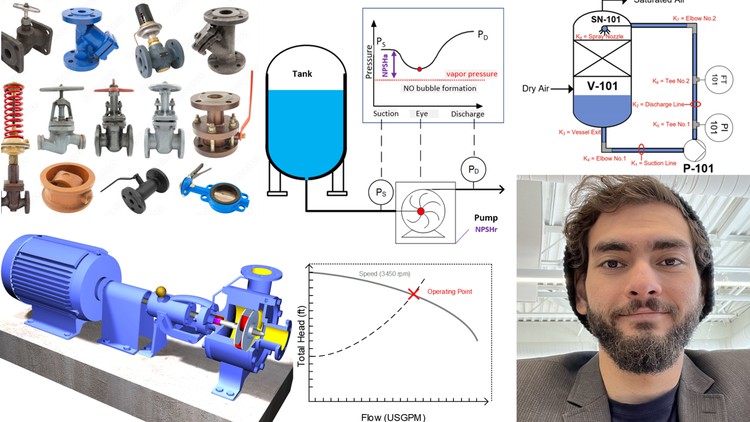
Modeling of piping systems, components, fittings and valves for incompressible fluid.
Understand the Darcy equation, resistance coefficient (K), friction factor (f), flow coefficient (Cv), and orifice design.
Identify and understand the basic components of a pump and calculate pumps Hydraulic Horsepower , Brake Horsepower , Pump Efficiency, Motor Power & Motor Eff.
Understand pump curves for different impeller speeds (or diameters), pump efficiency curves, pump NPSHr curves and Power consumption curves.
Develop a roadmap for proper selection of pumps via excel macros and model resistance in series for a piping system.
Understand inherent valve curves, different types of control valves, valve authority, and size valves appropriately for a given system.
Description
Chapter 1: Introduction
1. Differentiate between incompressible and compressible fluids using the continuity equation.
2. Define and understand general concepts in fluid dynamics, such as viscosity (dynamic and kinematic), Reynolds number (laminar and turbulent flow), and volumetric flow rate.
Chapter 2: Energy Balance
3. Derive and apply the Bernoulli equation to develop an energy balance for sizing pumps.
4. Understand the pump equation and its relation to the Bernoulli equation.
5. Apply the pump equation to an illustrative example.
6. Create system curves for a piping system.
Chapter 3: Friction Headloss
7. Understand hydraulic resistances in pipes.
8. Define the Darcy equation and its application in calculating frictional headloss.
9. Define the resistance coefficient (K) and calculate it using different methods.
10. Define the friction factor (f) and calculate it using numerical methods via the Poiseuille equation, Colebrook equation, Swamee Jain equation, or the Moody chart.
11. Understand the effect of pipe age on friction factor.
12. Define flow coefficient (Cv) and its application in calculating pressure drop.
13. Adjust Cv for liquids with different viscosities.
14. Find the capacity flow rate at different pressure drops for a given Cv.
15. Convert flow coefficient (Cv) to a resistant coefficient (K).
16. Understand the use of orifice plates and use the orifice design equation to size orifice plates.
17. Apply the orifice design equation in an illustrative example.
Chapter 4: Pumps
18. Identify and understand the basic components of a pump.
19. Calculate pumps Hydraulic Horsepower (HHP), Brake Horsepower (BHP), Pump Efficiency, Motor Power (MP), and Motor Efficiency through an example.
20. Understand pump curves (head vs flow rate) for different impeller speeds (or diameters).
21. Understand pump efficiency curves.
22. Understand Pumps Net Positive Suction Head Required (NPSHr) Curve.
23. Understand Pump Power Consumption Curve.
Chapter 5: System Modeling and Pump Sizing Roadmap
24. Model resistance in series for a piping system.
25. Develop a roadmap for proper selection of pumps.
Chapter 6: Case Study 1
26. Apply the pump sizing roadmap using Macros in Excel to select an appropriate pump for a real-world case study.
Chapter 7: Control Valves
27. Identify different types of control valves and their applications.
28. Understand the inherent valve curve and its relation to flow rate and pressure drop.
29. Define valve authority and its significance in valve selection.
30. Size valves appropriately for a given system.
Content
