Microcontrollers
What you will learn
On completion of this course student will describe the architecture of 8051and the organization of 8051 microcontroller
On completion of this course student will Identify the Instruction set and addressing modes of 8051 microcontroller
On completion of this course student will Develop programming skills in assembly language
On completion of this course student will Explain the need for different interfacing devices.
Description
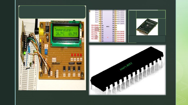
8051 microcontroller was designed in 1981 by INTEL. In this course I am going discuss difference between microprocessor and microcontroller. 8051 microcontroller is designed by Intel in 1981. It is an 8-bit microcontroller. It is built with 40 pins DIP (dual inline package), 4kb of ROM storage and 128 bytes of RAM storage, 2 16-bit timers. It consists of are four parallel 8-bit ports, which are programmable as well as addressable as per the requirement. An on-chip crystal oscillator is integrated in the microcontroller having crystal frequency of 11.0592MHz.
Basic structure of ALU and registers. Block diagram of 8051 microcontroller. register organization of 8051 microcontroller, pin diagram of 8051 microcontroller. Function of special registers, Addressing modes and Instruction set of 8051 microcontroller.
Assembly language Programming, Memory interfacing, Interfacing with peripheral ICs 8251- serial I/O, 8255-parallel I/O ( The 8255A is a general purpose programmable I/O device designed to transfer the data from I/O to interrupt I/O under certain conditions as required. It can be used with almost any microprocessor.
It consists of three 8-bit bidirectional I/O ports (24I/O lines) which can be configured as per the requirement.) ,
8257-DMA( DMA stands for Direct Memory Access. It is designed by Intel to transfer data at the fastest rate. It allows the device to transfer the data directly to/from memory without any interference of the CPU.
Using a DMA controller, the device requests the CPU to hold its data, address and control bus, so the device is free to transfer data directly to/from the memory. The DMA data transfer is initiated only after receiving HLDA signal from the CPU.) ,
8259 PIC( The 8259 is known as the Programmable Interrupt Controller (PIC) microprocessor. This chip combines the multi-interrupt input source to single interrupt output. This provides 8-interrupts from IR0 to IR7.
The 8259A was the interrupt controller for the ISA bus in the original IBM PC and IBM PC AT. By connecting 8259 with the CPU, we can increase the interrupt handling capability. ),
8251 USART, serial communication and types of serial communication. 8051 microcontrollers have 4 I/O ports each of 8-bit, which can be configured as input or output. Hence, total 32 input/output pins allow the microcontroller to be connected with the peripheral devices.
Input Configuration
If any pin of this port is configured as an input, then it acts as if it “floats”, i.e. the input has unlimited input resistance and in-determined potential.
Output Configuration
When the pin is configured as an output, then it acts as an “open drain”. By applying logic 0 to a port bit, the appropriate pin will be connected to ground (0V), and applying logic 1, the external output will keep on “floating”. 8051 has 5 interrupt signals, i.e. INT0, TFO, INT1, TF1, RI/TI. Each interrupt can be enabled or disabled by setting bits of the IE register and the whole interrupt system can be disabled by clearing the EA bit of the same register.
Content
